Friday 29 June 2012

LIFT: MaNuFaCtUrErS iN dElHi


In agriculture and manufacturing, an elevator is any type of conveyor device used to lift materials in a continuous stream into bins or silos. Several types exist, such as the chain and bucket bucket elevator, grain auger screw conveyor using the principle of Archemede’s principle, or the chain and paddles/forks of hay elevators .Languages other than English may have loanwords based on either elevator or lift.
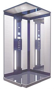
Because of wheelchair access laws, elevators are often a legal requirement in new multistory buildings, especially where wheelchair ramps would be impractical. Some people argue that elevators began as simple rope or chain hoists (see Traction elevators below). A elevator is essentially a platform that is either pulled or pushed up by a mechanical means. A modern day elevator consists of a cab (also called a "cage" or "car") mounted on a platform within an enclosed space called a shaft or sometimes a "hoistway".
 In the past, elevator drive mechanisms were powered by steam and water hydraulic pistons or by hand. In a "traction" elevator, cars are pulled up by means of rolling steel ropes over a deeply grooved pulley, commonly called a sheave in the industry.

The weight of the car is balanced by a counterweight. Sometimes elevators lifts always move synchronously in opposite directions, and they are each other's counterweight.


The friction between the ropes and the pulley furnishes the traction which gives this type of lift its name.
Hydraulic elevators use the principles of hydraulics (in the sense of hydraulic power) to pressurize an above ground or in-ground piston to raise and lower the car (see Hydraulic elevators below). Roped hydraulics use a combination of both ropes and hydraulic power to raise and lower cars. Recent innovations include permanent magnet motors, machine room-less rail mounted gearless machines, and microprocessor controls.
The technology used in new installations depends on a variety of factors. Hydraulic elevators are cheaper, but installing cylinders greater than a certain length becomes impractical for very high lift hoistways. For buildings of much over seven storys, traction lifts must be employed instead. Hydraulic elevators are usually slower than traction lifts.

Elevators are a candidate for mass customization. There are economies to be made from mass production of the components, but each building comes with its own requirements like different number of floors, dimensions of the well and usage patterns.
Elevator doors protect riders from falling into the shaft. The most common configuration is to have two panels that meet in the middle, and slide open laterally. In a cascading telescopic configuration (potentially allowing wider entryways within limited space), the doors run on independent tracks so that while open, they are tucked behind one another, and while closed, they form cascading layers on one side. This can be configured so that two sets of such cascading doors operate like the center opening doors described above, allowing for a very wide elevator cab.

 In less expensive installations the elevator can also use one large "slab" door: a single panel door the width of the doorway that opens to the left or right laterally. Some buildings have elevators with the single door on the shaft way, and double cascading doors on the cab.

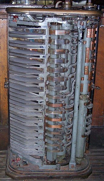
Geared traction machines are driven by AC or DC electric motors. Geared machines use wormgears to control mechanical movement of elevator cars by "rolling" steel hoist ropes over a drive sheave which is attached to a gearbox driven by a high speed motor. These machines are generally the best option for basement or overhead traction use for speeds up to 500 ft/min (2.5 m/s). In order to allow accurate speed control of the motor, to allow accurate levelling and for passenger comfort, a DC hoist motor powered by an AC/DC motor- generator (MG) set was the preferred solution in high-traffic elevator installations for many decades.
The MG set also typically powered the relay controller of the elevator, which has the added advantage of electrically isolating the elevators from the rest of a building's electrical system, thus eliminating the transient power spikes in the building's electrical supply caused by the motors starting and stopping (causing lighting to dim every time the elevators are used for example), as well as interference to other electrical equipment caused by the arcing of the relay contactors in the control system.
Contemporary cheaper installations, such as those in residential buildings and low-traffic commercial applications generally used a single or two speed AC hoist machine. The widespread availability of cheap solid state AC drives has allowed infinitely variable speed AC motors to be used universally, bringing with it the advantages of the older motor-generator based systems, without the penalties in terms of efficiency and complexity. The older MG-based installations are gradually being replaced in older buildings due to their poor energy efficiency.
Gearless traction machines are low speed (low RPM), high torque electric motors powered either by AC or DC. In this case, the drive sheave is directly attached to the end of the motor. Gearless traction elevators can reach speeds of up to 2,000 ft/min (10 m/s), or even higher. A brake is mounted between the motor and drive sheave (or gearbox) to hold the elevator stationary at a floor. This brake is usually an external drum type  and is actuated by spring force and held open electrically; a power failure will cause the brake to engage and prevent the elevator from falling (see inherent safety and safety engineering).
In each case, cables are attached to a hitch plate on top of the cab or may be "underslung" below a cab, and then looped over the drive sheave to a conterweight attached to the opposite end of the cables which reduces the amount of power  needed to move the cab. The counterweight is located in the hoist-way and rides a separate railway system; as the car goes up, the counterweight goes down, and vice versa. This action is powered by the traction machine which is directed by the controller, typically a relay logic or computerized device that directs starting, acceleration  , deceleration and stopping of the elevator cab.
The weight of the counterweight is typically equal to the weight of the elevator cab plus 40-50% of the capacity of the elevator. The grooves in the drive sheave are specially designed to prevent the cables from slipping. Traction is provided to the ropes by the grip of the grooves in the sheave, thereby the name. As the ropes age and the traction grooves wear, some traction is lost and the ropes must be replaced and the sheave repaired or replaced. Sheave and rope wear may be significantly reduced by ensuring that all ropes have equal tension, thus sharing the load evenly. Rope tension equalisation may be achieved using a rope tension gauge, and is a simple way to extend the lifetime of the sheaves and ropes.
Elevators with more than 100 ft (30 m) of travel have a system called compensation. This is a separate set of cables or a chain attached to the bottom of the counterweight and the bottom of the elevator cab. This makes it easier to control the elevator, as it compensates for the differing weight of cable between the hoist and the cab.
If the elevator cab is at the top of the hoist-way, there is a short length of hoist cable above the car and a long length of compensating cable below the car and vice versa for the counterweight. If the compensation system uses cables, there will be an additional sheave in the pit below the elevator, to guide the cables. If the compensation system uses chains, the chain is guided by a bar mounted between the counterweight railway lines.


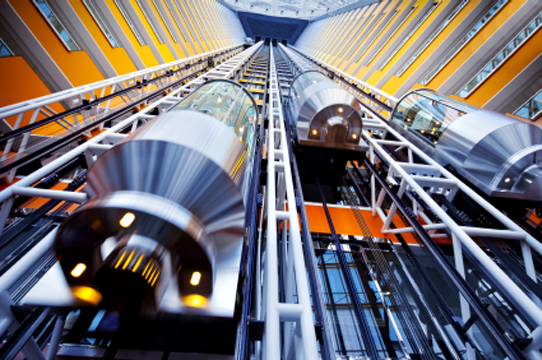
An elevator is a type of vertical transport equipment that efficiently moves people or goods between floors (levels, decks) of a building, vessel or other structures. Elevators are generally powered by electric motors that either drive traction cables or counterweight systems like a hoist, or pump hydraulic fluid to raise a cylindrical piston like a jack.

Electrical switchgear suppliers


File:Hybrid switchgear.jpg


File:Tram switchgear.JPG


Switchgear is often inspected using thermal imaging to assess the state of the system and predict failures before they occur. Other methods include partial discharge (PD) testing, using either fixed or portable testers, and acoustic emission testing using surface-mounted transducers (for oil equipment) or ultrasonic detectors used in outdoor switchyards. Temperature sensors fitted to cables to the switchgear can permanently monitor temperature build-up. SF6 equipment is invariably fitted with alarms and interlocks to warn of loss of pressure, and to prevent operation if the pressure falls too low.

File:Switchgear HV.jpgIn an electric power system, switchgear is the combination of disconnect switches, fuses or circuit breakers used to control, protect and isolate electrical equipment. Switchgear is used both to de-energize equipment to allow work to be done and to clear faults downstream. This type of equipment is important because it is directly linked to the reliability of the electricity supply.

The very earliest central power stations used simple open knife switches, mounted on insulating panels of marble or asbestos. Power levels and voltages rapidly escalated, making opening manually operated switches too dangerous for anything other than isolation of a de-energized circuit. Oil-filled equipment allowed arc energy to be contained and safely controlled. By the early 20th century, a switchgear line-up would be a metal-enclosed structure with electrically operated switching elements, using oil circuit breakers. Today, oil-filled equipment has largely been replaced by air-blast, vacuum, or SF6 equipment, allowing large currents and power levels to be safely controlled by automatic equipment incorporating digital controls, protection, metering and communications.

File:IndustrialSwitchgear.JPGHigh voltage switchgear was invented at the end of the 19th century for operating motors and other electric machines.  The technology has been improved over time and can be used with voltages up to 1,100 kV .

Typically, the switchgear in substations is located on both the high voltage and the low voltage side of large power transformers. The switchgear on the low voltage side of the transformers may be located in a building, with medium-voltage circuit breakers for distribution circuits, along with metering, control, and protection equipment. For industrial applications, a transformer and switchgear line-up may be combined in one housing, called a unitized substation or USS.
Switchgear for low voltages may be entirely enclosed within a building. For transmission levels of voltage (high voltages over 66 kV), often switchgear will be mounted outdoors and insulated by air, although this requires a large amount of space. Gas insulated switchgear used for transmission-level voltages saves space compared with air-insulated equipment, although it has a higher equipment cost. Oil insulated switchgear presents an oil spill hazard.

At small substations, switches may be manually operated, but at important switching stations on the transmission network all devices have motor operators to allow for remote control.
A piece of switchgear may be a simple open-air isolator switch or it may be insulated by some other substance. An effective although more costly form of switchgear is gas insulated switchgear (GIS), where the conductors and contacts are insulated by pressurized sulfur hexafluoride gas (SF6). Other common types are oil or vacuum insulated switchgear.

The combination of equipment within the switchgear enclosure allows them to interrupt fault currents of thousands of amps. A circuit breaker (within a switchgear enclosure) is the primary component that interrupts fault currents. The quenching of the arc when the circuit breaker pulls apart the contacts open (disconnects the circuit) requires careful design. Circuit breakers fall into these four types:

Oil: Oil circuit breakers rely upon vaporization of some of the oil to blast a jet of oil through the arc.
Gas: Gas (SF6) circuit breakers sometimes stretch the arc using a magnetic field, and then rely upon the dielectric strength of the SF6 to quench the stretched arc.
Vacuum:Vacuum circuit breakers have minimal arcing (as there is nothing to ionize other than the contact material), so the arc quenches when it is stretched to a very small amount (<2–3 mm). At or near current zero the arc is not hot enough to maintain a plasma, and current ceases; the gap can then withstand the rise of voltage. Vacuum circuit breakers are frequently used in modern medium-voltage switchgear to 35,000 volts. Unlike the other types, they are inherently unsuitable for interrupting DC faults.
To help ensure safe operation sequences of switchgear, trapped key interlocking provides predefined scenarios of operation. For example, if only one of two sources of supply are permitted to be connected at a given time, the interlock scheme may require that the first switch must be opened to release a key that will allow closing the second switch. Complex schemes are possible.

Indoor switchgear can also be type tested for internal arc containment (e.g. IEC 62271-200). This test is important for user safety as modern switchgear is capable of switching large currents.


The increasing awareness of dangers associated with high fault levels has resulted in network operators specifying closed door operation for operating earth switches and racking breakers. Many European power companies have banned operators from switch rooms while operating. Remote racking systems are available which allow an operator to rack switchgear from a remote location without the need to wear a protective arc flash hazard suit.

A single line-up may incorporate several different types of devices, for example, air-insulated bus, vacuum circuit breakers, and manually operated switches may all exist in the same row of cubicles.

Ratings, design, specifications and details of switchgear are set by a multitude of standards. In North America mostly IEEE and ANSI standards are used, much of the rest of the world uses IEEEstandards, sometimes with local national derivatives or variations. The content is taken from wikipidea.


The Latest Switchgears


Be it energy supply corporations, industry or power stations, any owner or user of primary distribution systems for medium voltage, places high demands on the switchgear. These include reliable technology, ease of operation and economy. With our complete range of circuit breaker and switchgear systems for medium voltage, Siemens Switchgears sets the standards when it comes to reliable and efficient solutions for switching requirements.

Siemens is a market leader in the study and implementation of Vacuum Technology, which is now the most preferred interrupting medium for Medium Voltage Circuit Breakers. In the Air Insulated Indoor Switchgear, Siemens offers Switchgear-Panels with Vacuum Circuit Breakers from 3.3kV to 36kV Voltage range.


As a pioneer in air-insulated and gas-insulated switchgear, Siemens has 25 years of know-how in the development of switchgear and switching devices. Customers can take full advantage of this technology. Since the power demand for processes in the oil & gas industry is increasing, Siemens Energy is covering this high rated-current and short-circuits demand with air-insulated (up to 38 kV) and gas-insulated medium-voltage (MV) switchgear (up to 40.5 kV).

The MV gas-insulated switchgear at a glance:
  • Compact and modular design.
  • Reduced footprint .
  • Maintenance-free .
  • Independent of pollution and humidity .
  • Motor load for the oil & gas processes: In excess of 80% of the project power .
The MV air-insulated switchgear at a glance:
  • Withdraw able design
  • Fused contactor feeder panels (only half the width of a circuit-breaker panel)
  • Both the air-insulated and the gas-insulated switchgear have an extremely good safety record with high reliability and availability.
The Siemens low-voltage (LV) switchboard has a modular design with high combination flexibility. Adaptations for new performance demands during operation can be carried out easily by exchanging the withdrawable units or changing the compartments. The LV switchboard is available in a fixed-mounted, plug-in and fully withdrawable design and as a Motor Control Centre (MCC).

Global capabilities for switchgear and switchboard :
Siemens has global engineering and manufacturing capabilities for our medium-voltage and low-voltage switchgear and switchboard and holds important approvals and certifications for onshore and offshore applications in oil and gas.

Wide Range Of ANALOG VOLTMETERS

A voltmeter is an instrument used for measuring electrical potential difference between two points in an electric circuit. Analog voltmeters move a pointer across a scale in proportion to the voltage of the circuit; digital voltmeters give a numerical display of voltage by use of an analog to digital converter.


Analog Voltmeters are made in a wide range of styles. Instruments permanently mounted in a panel are used to monitor generators or other fixed apparatus. Portable instruments, usually equipped to also measure current and resistance in the form of a multimeter, are standard test instruments used in electrical and electronics work. Any measurement that can be converted to a voltage can be displayed on a meter that is suitably calibrated; for example, pressure, temperature, flow or level in a chemical process plant.

General purpose analog voltmeters may have an accuracy of a few percent of full scale, and are used with voltages from a fraction of a volt to several thousand volts. Digital meters can be made with high accuracy, typically better than 1%. Specially calibrated test instruments have higher accuracies, with laboratory instruments capable of measuring to accuracies of a few parts per million. Meters using amplifiers can measure tiny voltages of microvolts or less.

Part of the problem of making an accurate voltmeter is that of calibration to check its accuracy. In laboratories, the Weston Cell is used as a standard voltage for precision work. Precision voltage references are available based on electronic circuits.

A moving coil galvanometer can be used as a voltmeter by inserting a resistor in series with the instrument. It employs a small coil of fine wire suspended in a strong magnetic field. When an electric current is applied, the galvanometer's indicator rotates and compresses a small spring. The angular rotation is proportional to the current through the coil. For use as a voltmeter, a series resistance is added so that the angular rotation becomes proportional to the applied voltage.

One of the design objectives of the instrument is to disturb the circuit as little as possible and so the instrument should draw a minimum of current to operate. This is achieved by using a sensitive ammeter or micro ammeter in series with a high resistance.

The sensitivity of such a meter can be expressed as "ohms per volt", the number of ohms resistance in the meter circuit divided by the full scale measured value. For example a meter with  sensitivity of 1000 ohms per volt would draw 1 milli ampere at full scale voltage; if the full scale was 200 volts, the resistance at the instrument's terminals would be 200,000 ohms and at full scale the meter would draw 1 milli ampere from the circuit under test. For multi-range instruments, the input resistance varies as the instrument is switched to different ranges.

analog voltmeter cirsuit using Operational Amplifier.

Moving-coil instruments with a permanent-magnet field respond only to direct current. Measurement of AC voltage requires a rectifier in the circuit so that the coil deflects in only one direction. Moving-coil instruments are also made with the zero position in the middle of the scale instead of at one end; these are useful if the voltage reverses its polarity.

Voltmeters operating on the electrostatic principle use the mutual repulsion between two charged plates to deflect a pointer attached to a spring. Meters of this type draw negligible current but are sensitive to voltages over about 100 volts and work with either alternating or direct current.

A moving coil galvanometer can be used as a voltmeter by inserting a resistor in series with the instrument. It employs a small coil of fine wire suspended in a strong magnetic field. When an electric current is applied, the galvanometer's indicator rotates and compresses a small spring. The angular rotation is proportional to the current through the coil. For use as a voltmeter, a series resistance is added so that the angular rotation becomes proportional to the applied voltage.

One of the design objectives of the instrument is to disturb the circuit as little as possible and so the instrument should draw a minimum of current to operate. This is achieved by using a sensitive ammeter or micro ammeter in series with a high resistance.

The sensitivity of such a meter can be expressed as "ohms per volt", the number of ohms resistance in the meter circuit divided by the full scale measured value. For example a meter with a sensitivity of 1000 ohms per volt would draw 1 milli ampere at full scale voltage; if the full scale was 200 volts, the resistance at the instrument's terminals would be 200,000 ohms and at full scale the meter would draw 1 milli ampere from the circuit under test. For multi-range instruments, the input resistance varies as the instrument is switched to different ranges.

Moving-coil instruments with a permanent-magnet field respond only to direct current. Measurement of AC voltage requires a rectifier in the circuit so that the coil deflects in only one direction. Moving-coil instruments are also made with the zero position in the middle of the scale instead of at one end; these are useful if the voltage reverses its polarity.

Voltmeters operating on the electrostatic principle use the mutual repulsion between two charged plates to deflect a pointer attached to a spring. Meters of this type draw negligible current but are sensitive to voltages over about 100 volts and work with either alternating or direct current.

The first digital voltmeter was invented and produced by Andrew Kay of Non-Linear Systems (and later founder of Kaypro) in 1954.

Digital voltmeters (DVMs) are usually designed around a special type of analog-to-digital converter called an integrating converter. Voltmeter accuracy is affected by many factors, including temperature and supply voltage variations. To ensure that a digital voltmeter's reading is within the manufacturer's specified tolerances, they should be periodically calibrated against a voltage standard such as the Weston cell.
Digital voltmeters necessarily have input amplifiers, and, like vacuum tube voltmeters, generally have a constant input resistance of 10 megohms regardless of set measurement range.


PC's for industrial use : InDuStRiAl Pc...

Computer industry  is a collective term used to describe the whole range of businesses involved in developing computer software , designing computer hardware  and computer networking  infrastructures, the manufacture of computer  components and the provision of information technology  services.
IBM released the 5531 Industrial Computer in 1984 arguably the first "industrial PC". The IBM 7531, an industrial version of the IBM AT PC was released May 21, 1985 Industrial Computer Source first offered the 6531 Industrial Computer in 1985. This was a proprietary 4U rackmount industrial computer based on a clone IBM PC motherboard.
Industrial PCs are used primarily for process control and/or data acquisition. In some cases, it is simply used as a front-end to another control computer in a distribute processing environment. Software can be custom written for a particular application or an off-the-shelf package such as Wonder Ware, Labtech Notebook or LabView can be used to provide a base level of programming.


An application may simply require the I/O such as the serial port offered by the motherboard. In other cases, expansion cards are installed to provide analog and digital I/O, specific machine interface, expanded communications ports, and so forth, as required by the application. They offer features different from consumer PCs in terms of reliability, compatibility, expansion options and long-term supply.

These are typically characterized by being manufactured in lower volumes than home or office PCs. A common category of this is the 19-inch rackmount form factor. They  typically cost considerably more than comparable office style computers with similar performance. Single-board computers and backplanes are used primarily in these systems. However, the majority of these are manufactured with COTS motherboards.

A subset of the system is the Panel PC where a display, typically an LCD, is incorporated into the same enclosure as the motherboard and other electronics. These are typically panel mounted and often incorporate touch screens for user interaction. They are offered in low cost versions with no environmental sealing, heavier duty models sealed to IP67 standards to be waterproof at the front panel and including models which are explosion proof for installation into hazardous environments.


Virtually all of them share an underlying design philosophy of providing a controlled environment for the installed electronics to survive the rigors of the plant floor. The electronic components themselves may be selected for their ability to withstand higher and lower operating temperatures than typical commercial components.
  • Heavier metal construction as compared to the typical office non-rugged computer
  • Enclosure form factor that includes provision for mounting into the surrounding environment (19" rack, wall mount, panel mount, etc.)
  • Alternative cooling methods such as forced air, liquid, and conduction.
  • Expansion card retention and support.
  • Enhanced EMI filtering and gasketing.
  • Enhanced environmental protection such as dust proof, water spray or immersion proof, etc.
  • Sealed MIL-SPEC or Circular-MIL connectors.
  • More robust controls and features.
  • Higher grade power supply.
  • Lower consumption 24 V power supply designed for use with DC UPS.
  • Controlled access to the controls through the use of locking doors.
  • Controlled access to the I/O through the use of access covers.
  • Inclusion of a watchdog timer to reset the system automatically in case of software lock-up.
·         Embedded systems span all aspects of modern life and there are many examples of their use.

·         Telecommunications systems employ numerous embedded systems from telephone switches for the network to mobile phones at the end-user. Computer networking uses dedicated routers and network bridges to route data.

·         Consumer electronics include personal digital assistants (PDAs), mp3 players, mobile phones, videogame consoles, digital cameras, DVD players, GPS receivers, and printers. Many household appliances, such as microwave ovens, washing machines and dishwashers, include embedded systems to provide flexibility, efficiency and features. Advanced HVAC systems use networked thermostats to more accurately and efficiently control temperature that can change by time of day and season. Home automation uses wired- and wireless-networking that can be used to control lights, climate, security, audio/visual, surveillance, etc., all of which use embedded devices for sensing and controlling.


·         Transportation systems from flight to automobiles increasingly use embedded systems. New airplanes contain advanced avionics such as inertial guidance systems and GPS receivers that also have considerable safety requirements. Various electric motors — brushless DC motors, induction motors and DC motors — use electric/electronic motor controllers. Automobiles, electric vehicles, and hybrid vehicles increasingly use embedded systems to maximize efficiency and reduce pollution. Other automotive safety systems include anti-lock braking system (ABS), Electronic Stability Control (ESC/ESP), traction control (TCS) and automatic four-wheel drive.

·         Medical equipment is continuing to advance with more embedded systems for vital signs monitoring, electronic stethoscopes for amplifying sounds, and various medical imaging (PET, SPECT, CT, MRI) for non-invasive internal inspections.

·         Embedded systems are especially suited for use in transportation, fire safety, safety and security, medical applications and life critical systems as these systems can be isolated from hacking and thus be more reliable. For fire safety, the systems can be designed to have greater ability to handle higher temperatures and continue to operate. In dealing with security, the embedded systems can be self-sufficient and be able to deal with cut electrical and communication systems.

·         In addition to commonly described embedded systems based on small computers, a new class of miniature wireless devices called motes are quickly gaining popularity as the field of wireless sensor networking rises. Wireless sensor networking, WSN, makes use of miniaturization made possible by advanced IC design to couple full wireless subsystems to sophisticated sensors, enabling people and companies to measure a myriad of things in the physical world and act on this information through IT monitoring and control systems. These motes are completely self contained, and will typically run off a battery source for many years before the batteries need to be changed or charged.

·         In certain applications, where small size or power efficiency are not primary concerns, the components used may be compatible with those used in general purpose x86 personal computers. Boards such as the VIA EPIA range help to bridge the gap by being PC-compatible but highly integrated, physically smaller or have other attributes making them attractive to embedded engineers. The advantage of this approach is that low-cost commodity components may be used along with the same software development tools used for general software development. Systems built in this way are still regarded as embedded since they are integrated into larger devices and fulfill a single role. Examples of devices that may adopt this approach are ATMs and arcade machines, which contain code specific to the application.

·         However, most ready-made embedded systems boards are not PC-centered and do not use the ISA or PCI busses. When a System-on-a-chip processor is involved, there may be little benefit to having a standarized bus connecting discrete components, and the environment for both hardware and software tools may be very different.


A common array of n configuration for very-high-volume embedded systems is the system on a chip (SoC) which contains a complete system consisting of multiple processors, multipliers, caches and interfaces on a single chip. SoCs can be implemented as an application-specific integrated circuit (ASIC) or using a field-programmable gate array (FPGA).
The information is taken from wikipedia.


Thursday 28 June 2012

Programmable Logic Controller : Omron PLC


 Many early PLCs did not have accompanying programming terminals that were capable of graphical representation of the logic, and so the logic was instead represented as a series of logic expressions in some version of Boolean format, similar to Boolean algebra. As programming terminals evolved, it became more common for ladder logic to be used, for the aforementioned reasons and because it was a familiar format used for electromechanical control panels. Newer formats such as State Logic and Function Block (which is similar to the way logic is depicted when using digital integrated logic circuits) exist, but they are still not as popular as ladder logic.
A primary reason for this is that PLCs solve the logic in a predictable and repeating sequence, and ladder logic allows the programmer (the person writing the logic) to see any issues with the timing of the logic sequence more easily than would be possible in other formats . Early PLCs, up to the mid-1980s, were programmed using proprietary programming panels or special-purpose programming terminals, which often had dedicated function keys representing the various logical elements of PLC programs.


 Programs were stored on cassette tape cartridges. Facilities for printing and documentation were minimal due to lack of memory capacity. The very oldest PLCs used non-volatile magnetic core memory. More recently, PLCs are programmed using application software on personal computers. The computer is connected to the PLC through Ethernet, RS-232, RS-485 or RS-422 cabling. The programming software allows entry and editing of the ladder-style logic. Generally the software provides functions for debugging and troubleshooting the PLC software, for example, by highlighting portions of the logic to show current status during operation or via simulation.


The software will upload and download the PLC program, for backup and restoration purposes. In some models of programmable controller, the program is transferred from a personal computer to the PLC through a programming board which writes the program into a removable chip such as an EEPROM or EPROM. In more recent years, small products called PLRs (programmable logic relays), and also by similar names, have become more common and accepted. These are very much like PLCs, and are used in light industry where only a few points of I/O (i.e. a few signals coming in from the real world and a few going out) are involved, and low cost is desired. These small devices are typically made in a common physical size and shape by several manufacturers, and branded by the makers of larger PLCs to fill out their low end product range. Popular names include PICO Controller, NANO PLC, and other names implying very small controllers. Most of these have between 8 and 12 digital inputs, 4 and 8 digital outputs, and up to 2 analog inputs. Size is usually about 4" wide, 3" high, and 3" deep. 


Most such devices include a tiny postage stamp sized LCD screen for viewing simplified ladder logic (only a very small portion of the program being visible at a given time) and status of I/O points, and typically these screens are accompanied by a 4-way rocker push-button plus four more separate push-buttons, similar to the key buttons on a VCR remote control, and used to navigate and edit the logic. Most have a small plug for connecting via RS-232 or RS-485 to a personal computer so that programmers can use simple Windows applications for programming instead of being forced to use the tiny LCD and push-button set for this purpose. 


Unlike regular PLCs that are usually modular and greatly expandable, the PLRs are usually not modular or expandable, but their price can be two orders of magnitude less than a PLC and they still offer robust design and deterministic execution of the logic. A PLC program is generally executed repeatedly as long as the controlled system is running. The status of physical input points is copied to an area of memory accessible to the processor, sometimes called the "I/O Image Table". The program is then run from its first instruction rung down to the last rung. It takes some time for the processor of the PLC to evaluate all the rungs and update the I/O image table with the status of outputs.[5] This scan time may be a few milliseconds for a small program or on a fast processor, but older PLCs running very large programs could take much longer (say, up to 100 ms) to execute the program. 


If the scan time was too long, the response of the PLC to process conditions would be too slow to be useful. As PLCs became more advanced, methods were developed to change the sequence of ladder execution, and subroutines were implemented.[6] This simplified programming and could also be used to save scan time for high-speed processes; for example, parts of the program used only for setting up the machine could be segregated from those parts required to operate at higher speed. Special-purpose I/O modules, such as timer modules or counter modules, can be used where the scan time of the processor is too long to reliably pick up, for example, counting pulses and interpreting  quadrature  from a shaft encoder. The relatively slow PLC can still interpret the counted values to control a machine, but the accumulation of pulses is done by a dedicated module that is unaffected by the speed of the program execution. PLCs may need to interact with people for the purpose of configuration, alarm reporting or everyday control. 

A human-machine interface (HMI) is employed for this purpose. HMIs are also referred to as man-machine interfaces (MMIs) and graphical user interface (GUIs). A simple system may use buttons and lights to interact with the user. Text displays are available as well as graphical touch screens. More complex systems use programming and monitoring software installed on a computer, with the PLC connected via a communication interface. PLCs are well adapted to a range of automation tasks. These are typically industrial processes in manufacturing where the cost of developing and maintaining the automation system is high relative to the total cost of the automation, and where changes to the system would be expected during its operational life.


PLCs contain input and output devices compatible with industrial pilot devices and controls; little electrical design is required, and the design problem centers on expressing the desired sequence of operations. PLC applications are typically highly customized systems, so the cost of a packaged PLC is low compared to the cost of a specific custom-built controller design.


 On the other hand, in the case of mass-produced goods, customized control systems are economical. This is due to the lower cost of the components, which can be optimally chosen instead of a "generic" solution, and where the non-recurring engineering charges are spread over thousands or millions of units. For high volume or very simple fixed automation tasks, different techniques are used. For example, a consumer dishwasher would be controlled by an electromechanical cam timer costing only a few dollars in production quantities. A microcontroller-based design would be appropriate where hundreds or thousands of units will be produced and so the development cost (design of power supplies, input/output hardware and necessary testing and certification) can be spread over many sales, and where the end-user would not need to alter the control. 
Automotive applications are an example; millions of units are built each year, and very few end-users alter the programming of these controllers. However, some specialty vehicles such as transit buses economically use PLCs instead of custom-designed controls, because the volumes are low and the development cost would be uneconomical. Very complex process control, such as used in the chemical industry, may require algorithms and performance beyond the capability of even high-performance PLCs. Very high-speed or precision controls may also require customized solutions; for example, aircraft flight controls. Single-board computers using semi-customized or fully proprietary hardware may be chosen for very demanding control applications where the high development and maintenance cost can be supported. "Soft PLCs" running on desktop-type computers can interface with industrial I/O hardware while executing programs within a version of commercial operating systems adapted for process control needs. Programmable controllers are widely used in motion control, positioning control and torque control.

Some manufacturers produce motion control units to be integrated with PLC so that G-code (involving a CNC machine) can be used to instruct machine movements. PLCs may include logic for single-variable feedback analog control loop, a "proportional, integral, derivative" or "PID controller". A PID loop could be used to control the temperature of a manufacturing process, for example. Historically PLCs were usually configured with only a few analog control loops; where processes required hundreds or thousands of loops, a distributed control system (DCS) would instead be used. As PLCs have become more powerful, the boundary between DCS and PLC applications has become less distinct. PLCs have similar functionality as Remote Terminal Units. An RTU, however, usually does not support control algorithms or control loops. 


As hardware rapidly becomes more powerful and cheaper, RTUs, PLCs and DCSs are increasingly beginning to overlap in responsibilities, and many vendors sell RTUs with PLC-like features and vice versa. The industry has standardized on the IEC 61131-3 functional block language for creating programs to run on RTUs and PLCs, although nearly all vendors also offer proprietary alternatives and associated development environments. 

In recent years "Safety" PLCs have started to become popular, either as standalone models ( Pilz PNOZ Multi, Sick etc.) or as functionality and safety-rated hardware added to existing controller architectures (Allen Bradley  Guardlogix , Siemens F-series etc.). These differ from conventional PLC types as being suitable for use in safety-critical applications for which PLCs have traditionally been supplemented with hard-wired safety relays. For example, a Safety PLC might be used to control access to a robot cell with trapped-key access, or perhaps to manage the shutdown response to an emergency stop on a conveyor production line. 
Such PLCs typically have a restricted regular instruction set augmented with safety-specific instructions designed to interface with emergency stops, light screens and so forth. The flexibility that such systems offer has resulted in rapid growth of demand for these controllers. Omron was established by Kazuma Tateishi in 1933 and incorporated in 1948. Omron's primary business is the manufacture and sale of automation components, equipment and systems, but it is generally known for medical equipment such as digital thermometers, blood pressure monitors and nebulizers.
Omron developed the world's first electronic ticket gate, which was named an IEEE Milestone in 2007, and was one of the first manufacturers of cash-dispensing ATMs with magnetic stripe card readers.

Smart Sensors


Keyence is a direct sales company; sales people visit customers on site with demonstration cases to show products. Keyence sensors, vision systems, and high definition microscopes are part of the manufacturing and research processes in a variety of industries, including the electronics, semiconductor, automotive, food and packaging, biotechnology, and pharmaceutical   industries . Keyence's customers include companies ranging from the largest Fortune 500 manufacturers to niche suppliers.

Keyence was named one of Business Week's “1000 Best Valued Companies.” Keyence Japan is consistently listed in the Nihon Keizai Shimbun's yearly ranking of the "Top Ten Most Excellent Companies in Japan." Keyence is known as one of the best "pay" companies in Japan. The average annual wage for all full-time employees (average age: 31.9 years old) in FY2006 was JPY13,860,000 (US$117,348 as of March 2007). A 350-million-year-old ammonite fossil is displayed at the entrance of the Japanese headquarters; other fossils of long-dead creatures align the corridors and meeting rooms. Relics are supposed to convey a tacit message to employees: keep aiming high or you'll become a fossil.

 
Takemitsu Takizaki founded Keyence Corporation in 1974 under the original name of "Lead Electric." Keyence is   fabless  (fabrication-less):  Although Keyence is a manufacturer; it specializes solely in product planning and development and does not manufacture the final products. Keyence products are manufactured at qualified contract manufacturing companies. Stephen Way, Senior Vice-President and Global Portfolio Manager at AGF Funds Inc.: "Keyence has a proven ability to deliver innovative products that customers want and this is driving strong pricing and profitability. The Financial Times: “Keyence means little to most people; to engineers, however, they mean a great deal.

Keyence manufactures a broad range of products, from photoelectric and proximity sensors to measuring instruments for inspection lines to high precision microscopy devices used in research institutes. These products are used by more than 80,000 customers globally. Products are shipped from Keyence's stocking network centers in Japan, U.S. (Chicago), the UK, Canada, Germany, Italy, France, Thailand, Malaysia, Singapore and South Korea or from 148 agents in 31 countries on the same day of receipt of an order. Keyence's customers in a variety of industries and manufacturing environments use their sensor products to detect the presence or absence of an entire part or just a particular feature of that part. Measurement products are used to determine the size or magnitude of a particular part or feature with great accuracy. New product releases consistently account for 30% of Keyence's annual sales. 

Vision system products are camera systems used on production lines to differentiate and measure multiple product features. Keyence's customers use their camera systems to perform quality control inspections that are too complicated for ordinary sensors. The IV "Vision Sensor" is a less expensive alternative to a full Vision system if all the capabilities of a Vision System are not needed. Their laser marking instruments use a high intensity laser to permanently and accurately mark shapes or characters onto surfaces such as metals or plastics at high speeds.
  • Machine Vision Sensor (IV Series)
  • Machine Vision (XG Series)
  • Machine Vision (CV Series)
  • Laser Marker (ML Series)
  • Laser Marker (MD Series)


Microscopes are the only products offered by Keyence America for use away from a production line. While many of the customers for their microscopes are manufacturers, these microscopes are more typically used for research and development or failure analysis applications. Keyence  Digital Microscopes  are capable of displaying a 3D image of the target. The image can also be manipulated or used to make a measurement of the target feature being viewed. Their color laser scanning microscope offers high accuracy with the use of a violet laser. This laser microscope approaches the accuracy and resolution of an SEM at a lower cost and without destroying the target. The information source is wikipedia .

Tuesday 26 June 2012

CRGO Toroidal Core Utilization in Transformers


The toroid is precious because they are inductors to protect the cables. The toroid also has self-inductance confrontation. The power of the self-inductance flourishes on the toroid numeral of spirals and alternating current resource. The plasma is a gas that holds liberated electromagnet, ions and only materialize at elevated heats. The inductors are used to sieve clamor on a direct current deliver stroke. A toroid is a strudel fashioned objective whose facade is a torus. Its globular silhouette is produce by rotating a ring around an alignment outside to the ring. The CRGO toroidal cores are moreover utilized in transformers or turbines in key energy stores. The toroidal coils transformer diminishes confrontation due to the superior distance and slighter numeral of meanderings. The captivating fluctuation in a toroid is cramped to the center and protects its power from organism engrossed by close substance. The directive is conversely equivalent to effectiveness, bodily size, cost, and is unswervingly relative to heat climb. These entire features must be taken into deliberation when the guideline space is indomitable. The most important reason of effluence fluctuation from any turbine is the atmosphere space. The captivating route or switch must have no atmosphere fissure. The toroidal core offers calm and proficient procedure with extremely squat drift captivating fields. They are miniature in size and heaviness hold a parcel that is unproblematic to develop into any submission. This fluctuation drifts into the environment owing to the elevated disinclination of the atmosphere and the attentiveness of fluctuation in the varnishes. The circumscription of the toroidal turbine unvaryingly encloses the center in copper mineral. The transformer or turbine is an appliance that relocates electric power from one switch to another through induction attached instrumentalists. The working hotness is a significant protection feature which should be measured. The extensive multiplicities of turbines mean are exercised in special function.