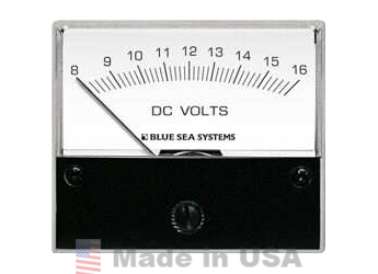
A voltmeter is an instrument used for measuring electrical potential difference between two points in an electric circuit. Analog voltmeters move a pointer across a scale in proportion to the voltage of the circuit; digital voltmeters give a numerical display of voltage by use of an analog to digital converter.
Analog Voltmeters are made in a wide range of styles. Instruments permanently mounted in a panel are used to monitor generators or other fixed apparatus. Portable instruments, usually equipped to also measure current and resistance in the form of a multimeter, are standard test instruments used in electrical and electronics work. Any measurement that can be converted to a voltage can be displayed on a meter that is suitably calibrated; for example, pressure, temperature, flow or level in a chemical process plant.
General purpose analog voltmeters may have an accuracy of a few percent of full scale, and are used with voltages from a fraction of a volt to several thousand volts. Digital meters can be made with high accuracy, typically better than 1%. Specially calibrated test instruments have higher accuracies, with laboratory instruments capable of measuring to accuracies of a few parts per million. Meters using amplifiers can measure tiny voltages of microvolts or less.
Part of the problem of making an accurate voltmeter is that of calibration to check its accuracy. In laboratories, the Weston Cell is used as a standard voltage for precision work. Precision voltage references are available based on electronic circuits.
 A moving coil galvanometer can be used as a voltmeter by inserting a resistor in series with the instrument. It employs a small coil of fine wire suspended in a strong magnetic field. When an electric current is applied, the galvanometer's indicator rotates and compresses a small spring. The angular rotation is proportional to the current through the coil. For use as a voltmeter, a series resistance is added so that the angular rotation becomes proportional to the applied voltage.
One of the design objectives of the instrument is to disturb the circuit as little as possible and so the instrument should draw a minimum of current to operate. This is achieved by using a sensitive ammeter or micro ammeter in series with a high resistance.
The sensitivity of such a meter can be expressed as "ohms per volt", the number of ohms resistance in the meter circuit divided by the full scale measured value. For example a meter with sensitivity of 1000 ohms per volt would draw 1 milli ampere at full scale voltage; if the full scale was 200 volts, the resistance at the instrument's terminals would be 200,000 ohms and at full scale the meter would draw 1 milli ampere from the circuit under test. For multi-range instruments, the input resistance varies as the instrument is switched to different ranges.
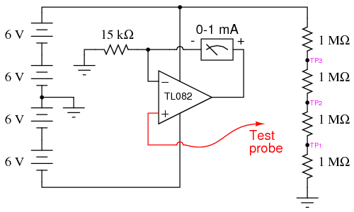 |
| analog voltmeter cirsuit using Operational Amplifier. |
Moving-coil instruments with a permanent-magnet field respond only to direct current. Measurement of AC voltage requires a rectifier in the circuit so that the coil deflects in only one direction. Moving-coil instruments are also made with the zero position in the middle of the scale instead of at one end; these are useful if the voltage reverses its polarity.
Voltmeters operating on the electrostatic principle use the mutual repulsion between two charged plates to deflect a pointer attached to a spring. Meters of this type draw negligible current but are sensitive to voltages over about 100 volts and work with either alternating or direct current.
 A moving coil galvanometer can be used as a voltmeter by inserting a resistor in series with the instrument. It employs a small coil of fine wire suspended in a strong magnetic field. When an electric current is applied, the galvanometer's indicator rotates and compresses a small spring. The angular rotation is proportional to the current through the coil. For use as a voltmeter, a series resistance is added so that the angular rotation becomes proportional to the applied voltage.
One of the design objectives of the instrument is to disturb the circuit as little as possible and so the instrument should draw a minimum of current to operate. This is achieved by using a sensitive ammeter or micro ammeter in series with a high resistance.
The sensitivity of such a meter can be expressed as "ohms per volt", the number of ohms resistance in the meter circuit divided by the full scale measured value. For example a meter with a sensitivity of 1000 ohms per volt would draw 1 milli ampere at full scale voltage; if the full scale was 200 volts, the resistance at the instrument's terminals would be 200,000 ohms and at full scale the meter would draw 1 milli ampere from the circuit under test. For multi-range instruments, the input resistance varies as the instrument is switched to different ranges.
Moving-coil instruments with a permanent-magnet field respond only to direct current. Measurement of AC voltage requires a rectifier in the circuit so that the coil deflects in only one direction. Moving-coil instruments are also made with the zero position in the middle of the scale instead of at one end; these are useful if the voltage reverses its polarity.
 Voltmeters operating on the electrostatic principle use the mutual repulsion between two charged plates to deflect a pointer attached to a spring. Meters of this type draw negligible current but are sensitive to voltages over about 100 volts and work with either alternating or direct current.
The first digital voltmeter was invented and produced by Andrew Kay of Non-Linear Systems (and later founder of Kaypro) in 1954.
Digital voltmeters (DVMs) are usually designed around a special type of analog-to-digital converter called an integrating converter. Voltmeter accuracy is affected by many factors, including temperature and supply voltage variations. To ensure that a digital voltmeter's reading is within the manufacturer's specified tolerances, they should be periodically calibrated against a voltage standard such as the Weston cell.
Digital voltmeters necessarily have input amplifiers, and, like vacuum tube voltmeters, generally have a constant input resistance of 10 megohms regardless of set measurement range.
No comments:
Post a Comment